Op-Amp Voltage Regulator Using a Zener Reference & NPN Transistor
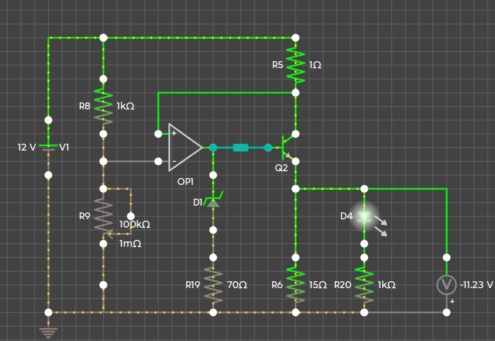
Circuit Diagram
Op-amp + Zener + NPN regulator
This schematic shows the full regulator: Zener reference, potentiometer divider, op-amp control loop, and NPN pass transistor.
This circuit is a compact and effective way to generate a stable DC voltage using an op-amp, a Zener diode, and an NPN transistor. It behaves as a closed-loop voltage regulator, keeping the output voltage steady even when the load resistance changes.
1. Zener Reference Network
Stable voltage reference
A Zener diode (≈11 V) is reverse‑biased through a 70 Ω resistor. This creates a stable reference voltage:
- ≈11 V across the Zener
- ≈1 V across the 70 Ω resistor
- ≈14 mA Zener current
This keeps the Zener in its proper regulation region, ensuring a clean and predictable reference voltage for the op-amp.
2. Adjustable Voltage Divider (R9)
Sets the output voltage
A potentiometer (R9) samples the Zener voltage and feeds an adjustable fraction of it into the op-amp’s input. Turning the pot changes the desired output voltage.
R9 is the main voltage control element of the regulator.
3. Op-Amp Control Loop
Closed-loop regulation
The op-amp compares:
- The reference voltage (Zener + R9)
- The actual output voltage (from the transistor emitter)
It then drives the base of the NPN transistor. The op-amp continuously adjusts its output so that the emitter voltage matches the reference voltage.
This closed-loop action is what stabilizes the output.
4. NPN Transistor as a Pass Element
Supplies the load
The NPN transistor (Q2) acts as a series pass transistor:
- The op-amp controls its base
- The emitter follows the base voltage minus VBE
- The load is powered from the emitter
Because the op-amp compensates for the VBE drop, the emitter voltage remains extremely stable.
5. Load Behavior
Voltage stays constant
When the load resistance changes:
- The output voltage stays constant (regulated)
- The current changes according to Ohm’s law
This is the defining behavior of a voltage regulator.
6. LED and Series Resistor
Part of the load
The LED and its series resistor (R20) are simply part of the load. They receive the regulated voltage from the emitter and behave normally regardless of load changes elsewhere.
Summary
Why this regulator works so well
This circuit is a straightforward and reliable DC voltage regulator:
- The Zener diode provides a stable reference.
- The potentiometer sets the desired output voltage.
- The op-amp compares the reference with the output.
- The NPN transistor supplies the load with a regulated voltage.
- The output voltage remains stable even as the load current varies.
It’s a clean example of how an op-amp can be used to build a precise, adjustable linear regulator with only a handful of components.