⚡ LM2576HV Adjustable Power Supply (1.2V–50V, 3A)
DIY Bench Supply Tutorial — Works with 12V, 24V, 36V, and 48V Inputs
📘 Circuit Diagram
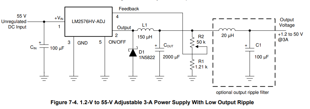
This is the complete LM2576HV‑ADJ adjustable power supply circuit used in this tutorial.
🔧 What This Power Supply Does
This project builds a simple adjustable DC power supply using the LM2576HV‑ADJ switching regulator. It accepts 12V, 24V, 36V, or 48V DC input and provides an adjustable output from 1.2V up to about 50V, depending on the input voltage. The LM2576HV is a high‑voltage buck converter capable of delivering up to 3A with good efficiency, making it ideal for DIY bench supplies, LED testing, motors, and general electronics.
🔌 Input and Output Voltage
The LM2576HV‑ADJ is a step‑down regulator, meaning the output voltage is always lower than the input. With a 12V input you can expect 1.2V to about 10V. With 24V input you can reach about 22V. With 36V input you can reach about 34V. With 48V input you can reach about 46V. The regulator requires roughly 2V of dropout between input and output, so the maximum output is always input minus about two volts.
🔥 Heatsink and Thermal Information
The LM2576HV is efficient but still produces heat depending on load and input voltage. Without a heatsink it can safely dissipate around 2 to 3 watts, which usually allows 0.5A to 1A depending on input voltage. With a medium aluminum heatsink it can dissipate around 8 to 12 watts, allowing the full 3A output in most cases. Higher input voltages increase heat, so a heatsink is strongly recommended for 24V, 36V, and 48V inputs.
⚠️ No Current Limiting
This design regulates voltage only. It does not limit current. If your load tries to draw more than 3A, the regulator will overheat or shut down. If you need current limiting you must add an external module such as a CC/CV buck converter or a dedicated current limiter board. For general electronics testing, LEDs, motors, and microcontrollers, this voltage‑only supply works well as long as you stay within the 3A limit.
🧩 Components Required
The build uses the LM2576HV‑ADJ regulator, a 100µF input capacitor rated at 63V or higher, a 150µH inductor rated for at least 3A, a 1N5822 Schottky diode, a 2000µF output capacitor rated at 63V or higher, a 1.21kΩ resistor for R1, a 50kΩ potentiometer for R2, optional 20µH and 100µF parts for extra ripple filtering, binding posts, wiring, perfboard or PCB, and a small aluminum heatsink.
🛠️ How the Circuit Works
The LM2576HV switches at 52kHz, feeding an inductor that smooths the voltage. The diode provides a return path during switching. The output capacitor filters the final voltage. The feedback network made from R1 and the 50kΩ potentiometer sets the output voltage. This design is simple, efficient, and reliable for beginners who want a stable adjustable supply.
🔧 Basic Build Steps
Connect the input capacitor to VIN and GND. Connect the inductor from the SW pin to the output node. Connect the diode from the output node to ground. Connect the output capacitor from the output node to ground. Wire the feedback resistor and potentiometer to the feedback pin. Mount the heatsink. Add binding posts and an optional voltmeter. After assembly, start with a low input voltage and verify the output with a multimeter.