DIY: Simple 12V DC Motor Control with Darlington BJT
Learn how to safely drive a 12V DC motor using a high-gain Darlington NPN transistor with pull-up resistor logic.
1. Circuit Schematic
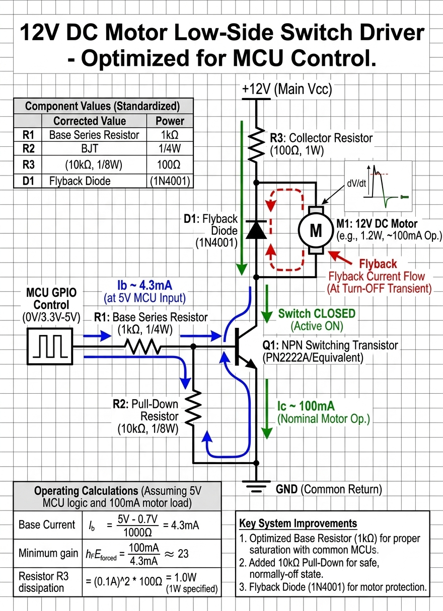
Below is the complete schematic diagram for the low-side Darlington motor switch:
2. Component List
- Transistor (Q1): TIP120 Darlington NPN BJT (or equivalent $h_{FE} > 1000$)
- Motor (M1): 12V DC Motor (~100mA nominal load)
- Flyback Diode (D1): 1N4001 General-Purpose Rectifier Diode
- Pull-Up Resistor (R2): 10kΩ, 1/8W
- Base Series Resistor (R1): 1kΩ, 1/4W
- Power Supply: +12V DC Main Rail & GND Common Return
3. How the Circuit Works
- High Current Gain: The TIP120 Darlington BJT combines two internal transistors, providing an extremely high current gain ($h_{FE} \ge 1000$). This allows tiny base signals to easily switch higher motor currents without overloading control circuitry.
- Pull-Up Active ON State: The 10kΩ pull-up resistor ($R_2$) holds the transistor base high when the input is floating, ensuring the transistor remains ON (Saturated) and the motor runs continuously by default.
- Safe Inductive Clamping: The antiparallel 1N4001 flyback diode ($D_1$) placed across the motor terminals safely redirects reverse inductive voltage spikes generated when the motor is switched off, protecting $Q_1$ from voltage breakdown.
4. Control Logic Reference
| Base Input Signal | Transistor State | Motor Operation |
|---|---|---|
| HIGH (5V - 12V) / High-Impedance (Floating) | ON (Saturated) | Motor Running |
| LOW (Pulled to 0V / GND) | OFF (Cut-off) | Motor Stopped |